The article describes in detail the diagram of the vacuum brake booster. It tells what it is and how it works.

Many car enthusiasts are faced with such a concept as a vacuum brake booster. It affects the increase in pressure created on the brake pads after the direct pressing of the gas pedal, which predetermines more comfortable driving conditions and less fatigue while driving.
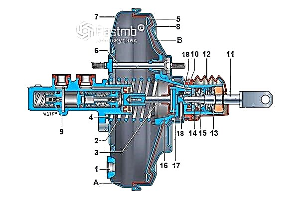
Vacuum brake booster circuit:

In this case, the device of such a vacuum brake booster is represented by a certain diagram, which includes the following elements:
- flange to strengthen the tip;
- return-type diaphragm spring;
- stock;
- O-ring used for the flange in the master cylinder;
- diaphragm;
- amplifier hairpin;
- amplifier case cover;
- the amplifier case itself;
- master brake cylinder;
- piston;
- pusher;
- protective cover for valve body;
- return-type pusher spring;
- follower valve;
- valve spring;
- valve body;
- stem buffer;
- channels.
If we consider in more detail each element used in the main device, then the following points should be noted. So, the amplifier body itself is divided into 2 cameras using a diaphragm:
A - vacuum chamber - facing the main brake cylinder;
B - atmospheric chamber - is in the opposite direction.
In this case, the connection of the vacuum chamber with the vacuum source is carried out through a check valve. The very same source of vacuum is the area located in the intake manifold of the engine itself, which comes after the throttle valve. Also, a vacuum-type electric pump can serve as a source of vacuum to provide uninterrupted operation of the car.
The atmospheric chamber, by means of a follower valve, is connected in the initial position with the vacuum-type chamber, and when the brake pedal is applied, with the atmosphere.
The follower is also connected to the brake pedal, allowing the follower valve to move. The diaphragm in the area of the vacuum chamber is connected to the rod in the piston master cylinder, which provides the diaphragm not only with movement, but also promotes the injection of brake fluid towards the wheel cylinders.
The return spring allows the diaphragm to return to its original position after the braking process has been completed.
The principle of operation of the used vacuum brake booster
The very work of a vacuum brake booster is based on providing a pressure difference in two types of chambers (vacuum and atmospheric). At the same time, in the initial period, the pressure in all chambers remains the same and is equal to the pressure that is obtained as a result of its creation by the vacuum source itself.
Subsequently, after pressing the brake pedal, the force is transmitted through the used pusher to the next valve, which already closes the channel between the vacuum and atmospheric chamber. Further, the movements of the valve lead to the connection of the vacuum chamber with the atmospheric one, as a result of which the vacuum in the latter decreases. The created pressure difference leads to the action on the diaphragm by overcoming the force created by the spring, and contributes to the movement of the piston rod in the master cylinder.
After the braking process is over, there is a reverse connection of the atmospheric and vacuum chambers and the subsequent equalization of the pressure in them. And the diaphragm, thanks to the action of the return spring, returns to its original state.
To find out about its breakdown, read the article on how to check a malfunction of a vacuum amplifier. If there are certain defects, then you should start replacing the vacuum brake booster.